
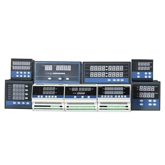
Description
PID temperature controller with multi channel can support not only temperature sensors, but also humidity sensor, pressure sensors, load cells, displacement sensors, liquid level sensors, gas sensors, and other non-standard sensors.
Specification:
| Model | ATO-TCDM |
| Weight | 0.5kg |
| Dimension (Length*High*Depth) * | D1: 160*80*80mm with hole size 152*76mm; D2: 96*96*110mm with hole size 92*92mm; D5: 72*72*110mm with hole size 68*68mm; D7: Rail type 107*88*59mm Note: D2, D5 and D7 apply to dual channels and four channels, and eight channels only has dimension D1. |
| Supply voltage | 85V-240V AC or 24V DC, 50-60Hz |
| Working environment | Temperature: -10~60℃, humidity: ≤90%RH |
| Sampling period | 8 times/second; When set digital filter parameter FILt=0, response time≤0.5s |
| Accuracy | ±0.5%F.S ±1 digit |
| Resolution | ≤0.01℃ |
| Input signal * | I1. Temperature sensor: CU50 (-50.0~150.0℃), PT100 (-199.9~600.0℃), K (-30.0~1300℃), E (-30.0~700.0℃), J (-30.0~900.0℃), T (-30.0~350.0℃), S (-30.0~1600℃) I2. Analog signal: 4-20mA, 0-10mA, 0-5V, 1-5V I3. I1+I2 all signals |
| Control mode | 1. On-off control; 2. PID control Need manually switch to another control mode. |
| Output mode * | O1: Relay output (AC 220V/5A of resistive load or AC 220V/0.3A of inductive load); O2: SSR output (Current ≥15mA, Voltage ≥9V); |
| Alarm mode * | A1 Default mode: 1 alarm output for each channel |
| Alarm | Upper limit, lower limit, upper deviation, lower deviation, in the deviation section, outside the deviation section; Temperature difference on each channel |
| Multi channel function | Multi channel can realize separate measuring and individual control |
| Additional output mode * | RS: RS485/232 communication (MODBUS-RTU protocol); PT: Printer (TTL232 print out) |
Wiring diagram:
1. PID temperature controller wiring diagram (input: I1 temerature sensor)
2. PID temperature controller wiring diagram (input: I2 analog signal)
3. PID temperature controller wiring diagram (input: I1+I2 all signals)
Tips: Difference between 4-20mA control signal and transmission signal?
The instrument can also support 4-20mA (including 0-10mA, 0-10V, 1-5V) as control signal output and transmission signal output. The control signal is used to control the output percentage of the VFD voltage regulating module. While the transmission signal converts the temperature values displayed on the current instrument into linear signal 4-20mA and then passes to PLC, DCS and other devices. Because PLC does not identify Pt100, K/E/J/T these temperature sensors, PLC can recognize the measured value only when it is ‘translated’ to 4-20mA signal by transmitter.
Reviews
There are no reviews yet.